Raspberry Pi · Single-board computer
Raspberry Pi 40-pin GPIO Header
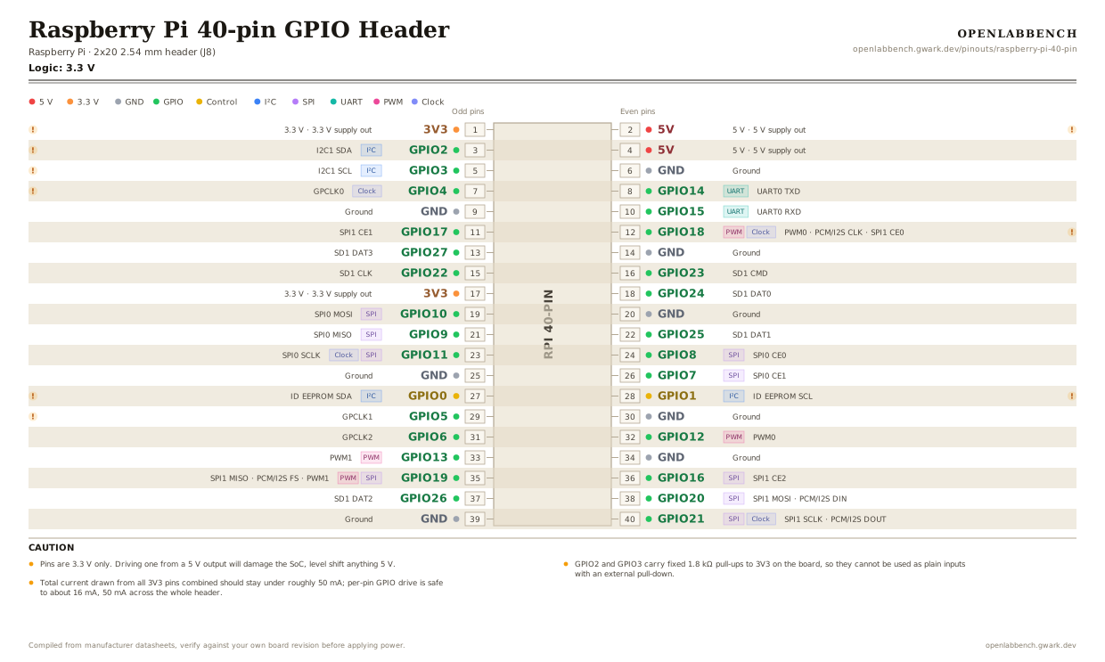
The J8 header shared by every 40-pin Raspberry Pi, from the Model B+ through the Pi 5. Names are BCM numbers, which is what libgpiod, pigpio and the Python GPIO libraries expect.
- Logic level
- 3.3 V
- Package
- 2x20 2.54 mm header (J8)
1.Pinout diagram
Highlight a signalhover to preview, click to keep
Odd pins
RPI 40-PIN
Even pins
Pin detail
Hover a pin for its mappings and gotchas. Click to keep it here.
- Logic level
- 3.3 V
- Package
- 2x20 2.54 mm header (J8)
Fig. 1. Raspberry Pi 40-pin GPIO Header, 2x20 2.54 mm header (J8). Hover or tap a signal to light up every pin that carries it.
2.Caution
- Pins are 3.3 V only. Driving one from a 5 V output will damage the SoC, level shift anything 5 V.
- GPIO2 and GPIO3 carry fixed 1.8 kΩ pull-ups to 3V3 on the board, so they cannot be used as plain inputs with an external pull-down.
- Total current drawn from all 3V3 pins combined should stay under roughly 50 mA; per-pin GPIO drive is safe to about 16 mA, 50 mA across the whole header.
- GPIO0/GPIO1 (pins 27/28) are reserved for HAT ID EEPROM detection. Avoid them unless you are building a HAT.
- Pin numbering is physical here. BCM (Broadcom) numbers are the pin names; the obsolete WiringPi scheme is a third numbering you will still see in old forum posts.
3.Full pin reference
Every pin, alias and mapping. This is the table that prints.
Table 1. Pin assignments.
| Pin | Name | Also called | Functions | Notes |
|---|---|---|---|---|
| 1 | 3V33.3 V | - | 3.3 V supply out | ~50 mA budget shared with pin 17. |
| 2 | 5V5 V | - | 5 V supply out | Fed straight from the USB-C / micro-USB input, upstream of the 3V3 regulator. |
| 3 | GPIO2I²C | BCM 2, SDA1, I2C1 SDA | I2C1 SDA | Fixed 1.8 kΩ pull-up to 3V3. |
| 4 | 5V5 V | - | 5 V supply out | |
| 5 | GPIO3I²C | BCM 3, SCL1, I2C1 SCL | I2C1 SCL | Fixed 1.8 kΩ pull-up to 3V3. Also wakes the Pi from halt when pulled low. |
| 6 | GND | - | Ground | |
| 7 | GPIO4Clock | BCM 4, GPCLK0 | GPCLK0 | Default 1-Wire bus pin (w1-gpio overlay), used by DS18B20 sensors. |
| 8 | GPIO14UART | BCM 14, TXD0, TXD | UART0 TXD | |
| 9 | GND | - | Ground | |
| 10 | GPIO15UART | BCM 15, RXD0, RXD | UART0 RXD | |
| 11 | GPIO17 | BCM 17 | SPI1 CE1 | |
| 12 | GPIO18PWMClock | BCM 18, PCM_CLK | PWM0, PCM/I2S CLK, SPI1 CE0 | The pin WS2812/NeoPixel libraries use, because it reaches PWM0 via DMA. |
| 13 | GPIO27 | BCM 27 | SD1 DAT3 | |
| 14 | GND | - | Ground | |
| 15 | GPIO22 | BCM 22 | SD1 CLK | |
| 16 | GPIO23 | BCM 23 | SD1 CMD | |
| 17 | 3V33.3 V | - | 3.3 V supply out | |
| 18 | GPIO24 | BCM 24 | SD1 DAT0 | |
| 19 | GPIO10SPI | BCM 10, MOSI | SPI0 MOSI | |
| 20 | GND | - | Ground | |
| 21 | GPIO9SPI | BCM 9, MISO | SPI0 MISO | |
| 22 | GPIO25 | BCM 25 | SD1 DAT1 | |
| 23 | GPIO11SPIClock | BCM 11, SCLK | SPI0 SCLK | |
| 24 | GPIO8SPI | BCM 8, CE0 | SPI0 CE0 | |
| 25 | GND | - | Ground | |
| 26 | GPIO7SPI | BCM 7, CE1 | SPI0 CE1 | |
| 27 | GPIO0I²C | BCM 0, ID_SD | ID EEPROM SDA | Reserved for HAT identification at boot. |
| 28 | GPIO1I²C | BCM 1, ID_SC | ID EEPROM SCL | Reserved for HAT identification at boot. |
| 29 | GPIO5 | BCM 5 | GPCLK1 | Pulling low wakes a halted Pi 4 / Pi 5. |
| 30 | GND | - | Ground | |
| 31 | GPIO6 | BCM 6 | GPCLK2 | |
| 32 | GPIO12PWM | BCM 12 | PWM0 | |
| 33 | GPIO13PWM | BCM 13 | PWM1 | |
| 34 | GND | - | Ground | |
| 35 | GPIO19SPIPWM | BCM 19, PCM_FS | SPI1 MISO, PCM/I2S FS, PWM1 | |
| 36 | GPIO16SPI | BCM 16 | SPI1 CE2 | |
| 37 | GPIO26 | BCM 26 | SD1 DAT2 | |
| 38 | GPIO20SPI | BCM 20, PCM_DIN | SPI1 MOSI, PCM/I2S DIN | |
| 39 | GND | - | Ground | |
| 40 | GPIO21SPIClock | BCM 21, PCM_DOUT | SPI1 SCLK, PCM/I2S DOUT |
Looking for a substitute?
Primary sources
Found a wrong pin? The whole board is one file, data/boards/raspberry-pi-40-pin.json.